
Since many years darktable offers a versatile tool for manual perspective correction in the crop & rotate module [1]. Although the principle is simple and straightforward, there are cases where it can prove difficult to get a convincing correction, especially if no distinct vertical or horizontal features can be spotted in the image. To overcome these limitations a new “perspective correction” module has just been added that is able to automatically correct for converging lines. The underlying mechanism is inspired by the program ShiftN developed by Marcus Hebel and published under the GPL [2].
Background
Perspective distortions are a natural effect when projecting a three dimensional scene onto a two dimensional plane photographically. As such they are not to be confused with lens errors which can be corrected in darktable’s lens correction module [3]. Perspective distortions cause objects close to the viewer to appear much larger than objects further away in the background. The closer you get to a subject the stronger the effect. As lenses with a short focal length force you to get closer to your subject, photos taken with wide angle lenses are more prone to show strong perspective distortions than telephoto lenses. Once again this is not an effect of the lens but an effect of the perspective (distance) of the viewer or camera to the scene.
Converging lines are a special case of perspective distortions frequently seen in architecture photographs. Parallel lines are an essential feature of most types of architecture; when photographed at an angle parallel lines get transformed into converging lines that meet at some vantage point within or outside the image frame.
Interestingly, viewers are mostly disturbed if they see a photo with converging lines that they know or assume to be vertical in reality. The reason seems to be that our brain is trained to unconsciously correct for vertical lines in the picture delivered by our eyes – vertical lines appear still vertical to us although the eye sees an image with converging lines as a camera would do. When watching the same scene in a photographic image the viewing situation is different and our brain does not apply its corrections. Now we clearly can identify the lines as converging and that conflicts to what we are used to see naturally.
There are a few ways to overcome this effect when taking a photo. One way is keeping the camera’s optical axis pointing to the horizon so that vertical lines run parallel to the sensor plane. However, this will bring a lot of potentially boring foreground into the lower part of the image which typically needs to be cropped afterward in image processing. Alternatively, one could use a shift lens [4] which gives more control on what part of the scene gets onto the camera sensor. Shift lenses tend to be heavy and expensive, so not everybody keeps them in his or her camera bag. That’s where perspective corrections in image processing come into play.
Working principle of the perspective correction module
Converging lines can be corrected by warping the image in such a way that the lines in question get parallel. The perspective correction module in darktable simulates the effects of a shift lens and – in its simplest form – only needs a single lens shift parameter to correct converging lines along one direction. Corrections can be done in vertical and horizontal direction, either separately or in combination.
Images quite often come with a tilted horizon. As we want lines not only to be parallel among themselves but also to align with the image frame the module additionally applies a rotation angle which is controlled by a further parameter.
Automatic corrections
Although a manual adjustment of the parameters is possible users will typically want to rely on the auto-correction feature of this module.
The principle way of working is as follows. darktable analyzes the image for structural features consisting of line segments. These line segments are evaluated and ranked to identify those lines which form a set of converging lines meeting in a vantage point. Please note that by far not all line segments in an image represent suited vertical or horizontal lines of the scene – it is crucial that unsuited lines are identified and eliminated from the set. Based on the remaining lines an automatic fitting procedure is then started that tries to identify the best values of the module parameters (rotation angle and lens shift in one direction, or rotation angle and lens shift in both directions) to get the image straight, i.e. adjust the converging lines to run parallel and/or horizontal to the image frame.

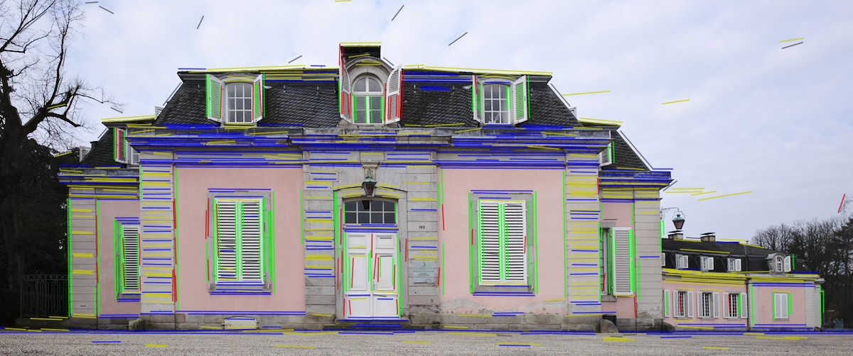
Pressing the “get structure” icon causes darktable to analyze the image for structural elements. Line segments are detected, evaluated and ranked. The line segments are then displayed as overlays on the image base. A color code tells you what type of line darktable has found:
- green lines that are selected as relevant vertical converging lines
- red lines that are vertical but are not part of the set of converging lines
- blue lines that are selected as relevant horizontal converging lines
- yellow lines that are horizontal but are not part of the set of converging lines
- grey lines that are detected but not of interest to this module
Lines marked in green and blue are taken for the further processing steps.
darktable is quite aggressive when it comes to marking lines in red or yellow, thus eliminating them from the set of selected lines. Reason is that we need to kick out unsuited lines as far as possible so that they do not negatively influence the following parameter fitting. This outlier elimination involves a statistical process with random sampling. As a consequence each time you press the “get structure” button the color pattern of the lines will look a bit different and some lines will get deselected that are obviously “good” ones. This is of no concern as long as all really unsuited lines are marked in red and yellow and as long as enough suited green and/or blue lines remain.
If you disagree with darktable’s decision you can always manually change it. Left-clicking on a line selects it (turns the color to green or blue) while right-clicking deselects it (turns the color to red or yellow). Keeping the mouse button pressed allows for a sweeping action to select/deselect multiple lines. Manual interaction is typically only needed if the line structure is distributed in a strongly inhomogeneous manner, e.g. all selected lines are on the right hand side of the image, none on the left. In this case you might need to manually select at least some lines on the left to allow for a successful automatic correction.
As this module needs to find straight lines, it is generally a good idea to have the image corrected for lens artifacts before line detection. You should therefore activate the lens correction module [3] before this one or click on the “get structure” icon again after having activated lens correction.
If your image exhibits a rather low contrast with few defined features the overall number of detected lines might be low. In this case you may try to ctrl-click on the “get structure” icon which activates an additional edge enhancing step before line detection. This leads to significantly more lines being detected.

Pressing the “clear structure” icon discards all collected structural information.

Pressing the “display structure” icon temporarily blocks the overlay display of lines so you have a better view of your image. Press the icon again to re-enable overlay display.
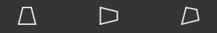
Pressing one of the “automatic fit” icons starts an optimization process which tries to detect the best fitting parameters for perspective correction of the image.
The leftmost icon performs an optimization of rotation angle and vertical lens shift based on selected vertical lines (the green ones).
The middle icon performs an optimization of rotation angle and horizontal lens shift based on selected horizontal lines (the blue ones).
The rightmost icon performs an optimization of all three parameters based on selected vertical as well as horizontal lines (the green and the blue ones). This typically leads to a compromise between the two other options.
In some cases you may want to only fit the rotation angle parameter while keeping the lens shift parameter(s) constant. You can do so by ctrl-clicking on one of the icons. The structural data used for fitting are the same as described above. Likewise you may shift-click on the icons to only fit the lens shift parameter(s) while keeping the rotation angle constant.
As a general rule all parameters that are not affected by the respective fitting step are kept constant.
One remark about correcting horizontal perspective distortions. Due to our way of living in a “mostly planar world” horizontal perspective distortions tend to be much stronger than vertical distortions in many images without viewers taking much notice. We are used to see converging horizontal lines, e.g. when looking along a street, and in fact we take advantage of them to estimate relative distances. However, that also means that horizontal lines tend to converge so strongly in a photographic image that it is out of the scope of this module to correct them. The horizontal vantage point may even lie within the image frame, giving a so called central perspective. For obvious reasons there is no way to correct for this image characteristic.
Further options
This module offers a number of further useful features which are controlled by a set of comboboxes in the middle part of the GUI.
The “guides” combobox lets you activate a set of horizontal and vertical guidelines laid over the image. You may use them to judge the quality of the automatic correction or let them assist you when doing manual adjustments.
The “automatic cropping” feature does what the name implies. When working with this module you will see immediately that any correction leads to more or less pronounced black corners around the warped image. You need to crop the image in order to get rid of the corners. This can be done either in the crop & rotate module [1], or by activating the “automatic cropping” combobox. “Largest area” finds the largest rectangular area which just fits into the warped image, while “original format” does the same with the additional prerequisite of keeping the aspect ratio of the original image.
Please note that you always see the full image as soon as the “perspective correction” module is in focus; cropping is not applied in order to grant a complete overview of the image. Automatic cropping, if activated, displays a frame around the cropping area that it has selected.
The example image above illustrates that you may lose a quite significant part of your image border when doing perspective corrections. You should take this into account when taking the shot and leave sufficient room around your main subject.
Of course the automatic cropping feature does not have any knowledge of the contents of your image – we recommend to use it in simple cases. Frequently you will want to have full artistic control on what parts of the image to crop; this power is only offered by the crop & rotate module [1]. We suggest to use either the automatic or the manual cropping option; combining both may lead to surprising results as soon as you change any parameters.
The “lens model” option controls some details of the underlying warping algorithm, namely the level of image compression perpendicular to the lens shift direction.
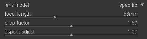
The default setting is “generic” which gives a realistic results in most cases. For images taken with a long focal length you may want to switch to “lens specific” which opens a number of sliders that let you define the focal length and the crop factor of your camera. You may also freely adjust the aspect ratio of the resulting image with the “aspect adjust” slider.
Availability
The new module has recently been added to the development branch of darktable [5]. It can be found in the “correction group” after activating it in “more modules”. Users of the unstable branch are invited to test it and give feedback. The usual disclaimer applies: as this module is still in the development phase we might change its behavior without further notice, don’t use it for productive work unless you know what you are doing. Users of the stable branch will see the final “perspective correction” module as part of darktable’s next feature release.
[ Update 18.03.16 ]
An updated version of this module has just been merged into the master branch. There is now a fourth adjustment parameter “shear” that warps the image along one of the diagonals. Together with the three other parameters this now allows to fully correct an image in almost all reasonable cases. Only perspective distortions so extreme, that they would lead to very poor image quality if corrected, are out of scope.
Clicking on the “fit both” icon (the rightmost in the automatic fit row) now finds optimal values for all four parameters. You get the former behavior of fitting only rotation and lens shift by ctrl-shift-clicking on that same icon.
A GUI enhancement suggested by Aldric has been added which allows to mass-select or deselect lines (changing their color from green/blue to red/yellow, or vice versa). You press the shift button and then draw a rectangular area on the image base. All lines within that area are being selected or deselected on button release. The left mouse button selects, the right mouse button deselects.


Well, we appreciate positive feedback and constructive input, so thanks for your positive response. We don't take financial donations but there are various ways to contribute, like testing, bug hunting, or contributing to translations.
Ulrich
Thank you
Just waiting to see it in a stable future release.
Unluckily, I am a windows user and just learning Darktable basics on windows built version by www.partha.com
Looks like i need to try some linux version to use all these excellent modules.
Great work by Darktable team, thanks to one and all.
Regarding a work-around for the current incompatibility of Sigma Foveon camera images with DT. There is a guy who has developed command-line software called Kalpanika that converts Foveon X3F files into DNG. His name is Roland Karlsson and can be contacted here: http://www.dpreview.com/members/6000522696/overview .
Would it make any sense if you and he worked together to allow DT to process X3F files into DNG that can be viewed and handled normally within DT? It would make a lot of sense to me as a DT and Sigma user! His Kalpanika project, basically a family effort, ran out of energy with a couple of issues still needing work. And the lack of a GUI is limiting. A bit of combined programmer horsepower for a mutual outcome, one that benefits marginalised Sigma camera users who, like Linux users, are not in the mainstream and need a little help from others. :) Sigma camera users are stuck with Sigma PhotoPro raw processor, which has numerous disadvantages.
thanks for reading this far (I hope)
Thanks!
Ulrich
TIA